EP0475024A1 - Schreibgerät, insbesondere Kugelschreiber - Google Patents
Schreibgerät, insbesondere Kugelschreiber Download PDFInfo
- Publication number
- EP0475024A1 EP0475024A1 EP91112089A EP91112089A EP0475024A1 EP 0475024 A1 EP0475024 A1 EP 0475024A1 EP 91112089 A EP91112089 A EP 91112089A EP 91112089 A EP91112089 A EP 91112089A EP 0475024 A1 EP0475024 A1 EP 0475024A1
- Authority
- EP
- European Patent Office
- Prior art keywords
- writing
- gas
- development cell
- wall
- gas development
- Prior art date
- Legal status (The legal status is an assumption and is not a legal conclusion. Google has not performed a legal analysis and makes no representation as to the accuracy of the status listed.)
- Withdrawn
Links
- 239000012530 fluid Substances 0.000 claims abstract description 12
- 239000012528 membrane Substances 0.000 claims description 4
- 239000004020 conductor Substances 0.000 claims description 3
- 230000004913 activation Effects 0.000 claims description 2
- 239000002184 metal Substances 0.000 description 6
- 241001422033 Thestylus Species 0.000 description 3
- 239000012777 electrically insulating material Substances 0.000 description 3
- 230000007423 decrease Effects 0.000 description 2
- 238000004519 manufacturing process Methods 0.000 description 2
- 238000007789 sealing Methods 0.000 description 2
- 238000004026 adhesive bonding Methods 0.000 description 1
- 239000011248 coating agent Substances 0.000 description 1
- 238000000576 coating method Methods 0.000 description 1
- 230000003247 decreasing effect Effects 0.000 description 1
- 238000006073 displacement reaction Methods 0.000 description 1
- 230000005489 elastic deformation Effects 0.000 description 1
- 238000000034 method Methods 0.000 description 1
- 238000012544 monitoring process Methods 0.000 description 1
- 235000011837 pasties Nutrition 0.000 description 1
- 230000002093 peripheral effect Effects 0.000 description 1
- 238000003825 pressing Methods 0.000 description 1
- 238000005086 pumping Methods 0.000 description 1
- 239000000126 substance Substances 0.000 description 1
- 238000003466 welding Methods 0.000 description 1
Images
Classifications
-
- B—PERFORMING OPERATIONS; TRANSPORTING
- B43—WRITING OR DRAWING IMPLEMENTS; BUREAU ACCESSORIES
- B43K—IMPLEMENTS FOR WRITING OR DRAWING
- B43K7/00—Ball-point pens
- B43K7/02—Ink reservoirs; Ink cartridges
- B43K7/03—Ink reservoirs; Ink cartridges pressurised, e.g. by gas
- B43K7/035—Ink reservoirs; Ink cartridges pressurised, e.g. by gas the gas acting on a piston
Definitions
- the invention relates to a writing instrument, in particular a ballpoint pen, with a writing tip provided at the front end of a writing body, with an axially displaceable feed piston arranged in the writing body, between which and the writing tip is provided in the writing body, and with a gas development cell arranged at the rear end of the writing body which, when its circuit is closed, generates a gas pressure which displaces the feed piston toward the writing tip.
- a fundamental problem with writing instruments that work with a writing fluid, in particular a pasty writing fluid, as is the case with ballpoint pens, is that the supply of writing fluid to the writing tip can be interrupted when the writing instrument is used in a position in which the writing tip lies above the remaining part of the writing body.
- a writing instrument of the type mentioned at the outset is designed in accordance with the invention in such a way that the gas development cell is located in a gas-tight space, the front wall of which is at least partially formed by the feed piston and the rear wall of which has a wall region which can be elastically deformed by the gas pressure generated, and that A contact element is provided on the side of the wall area facing the gas development cell, which is in contact with the gas development cell when the target gas pressure falls below due to a lack of deformation of the wall area and closes the circuit for its activation and which when a predetermined gas pressure is exceeded as a result of deformation of the wall area the gas development cell takes off.
- a gas development cell is thus used, as can also be used in the writing instrument according to the above-mentioned older German patent application P 40 13 011.8, which, as explained in the earlier application, when closing a circuit between its two main end faces in releases gas in a controlled manner, the voltage supply being integrated in the housing of the gas development cell.
- the feed piston of the writing instrument according to the invention is pressurized with a gas pressure when the pressure in the pen body has dropped below a desired value, for example because a corresponding amount of writing fluid has been consumed.
- the elastically deformable wall area comprising the contact element can be part of a preferably screwable cap that can be placed on the rear end of the pen body and that surrounds the gas development cell at least on the side and rear.
- this conductive material can form part of the circuit between the rear and the front surface of the gas pressure cell, in which the contact element also lies, if the wall area is in one position due to the lack of deformation is in which the contact element touches the rear surface of the gas development cell.
- the elastically deformable wall area can be formed, for example, by a membrane consisting essentially of plastic.
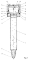
- the ballpoint pen shown has a tubular stylus body 1, in the front end of which a stylus 2 having a stylus 3 is inserted, which has an axially extending central opening which connects the interior of the stylus body 1 containing the paste 4 to the stylus 3.
- a feed piston 5 is provided, which is held in the writing body 1 in a sealing manner, but displaceable towards the front.
- annular collar 6, for example made of metal, is fastened, which has an external thread 7 and on the rear surface of which support projections 8 are formed.
- An O-ring 16 is arranged around the outer circumference of the support projections 8 on the rear side of the collar 6.
- a cap 9 can be screwed onto the external thread 7 of the collar 6, for which purpose the cap 9 has an internal thread 13 on its open side, at the inner end of which an annular projection is formed, which in the assembled state (FIGS and 3) comes into sealing contact with the O-ring 16.
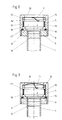
- the circumferential wall of the cap 9 and part of its bottom wall lying at the top in the figures are rigid and can consist of metal or can be coated on the inside with metal.
- the central opening in the bottom wall of the cap 9 is through an elastically deformable wall area 10, which consists, for example, of a plastic-coated plastic membrane on the surface facing the open side of the cap 9, which is elastically deformable and which is made of a existing electrically insulating material ring element 12 is fixed in its position in the bottom of the cap 9.
- the ring element 12 has contact projections 14, the function of which will be explained later, just like that of the axially extending abutment ribs 15 located on the inside of the peripheral wall of the cap 9.
- On the surface of the membrane 10 facing the opening of the cap 9 there is a Contact element 11 attached, which for example consist of a metal strip and can be attached to the wall area 10 by welding or gluing.
- a gas development cell 17 of a known type is used, which with its front surface, which forms the minus pole, on the support projections 8 of the Confederation 6.
- a layer 18 of electrically insulating material is arranged on the periphery of the gas development cell 17, and in the region of this layer 18 the support ribs 15 position the gas development cell 17 in the center and thus prevent its lateral displacement.
- the rear surface of the gas development cell 17 facing the contact element 11 forms the positive pole, which comes into contact with the contact element 11 when its cap 9 is screwed into the operating position according to FIGS. 2 and 3. In this operating position, the support projections 14 of the cap 9 are in engagement with the rear surface of the gas development cell 17. Since they are made of an electrically insulating material, they do not influence the gas development cell 17 electrically.
- the metallic coating of the wall area 10 the cap 9, which is made of metal, for example, and the collar 6, which is made of metal, becomes a circuit between the positive pole and the negative pole of the gas development cell 17 are closed, and this releases gas into the gas-tight space formed by the cap 9, collar 6, end surface of the pen body 1 and feed piston 5, thereby causing the feed piston 5 a pressure exerted on him in the direction of the column of writing paste 4 is exerted.
- the pressure built up also acts on the elastically deformable wall region 10, which deforms elastically when a predetermined gas pressure is reached in the manner indicated in FIG. 3, as a result of which the contact element 11 lifts off the rear surface of the gas development cell 17 and the circuit for it is thus interrupted.
- the gas development cell 17 therefore no longer emits gas.
Landscapes
- Pens And Brushes (AREA)
Applications Claiming Priority (2)
| Application Number | Priority Date | Filing Date | Title |
|---|---|---|---|
| DE19904027271 DE4027271C1 (en]) | 1990-08-29 | 1990-08-29 | |
| DE4027271 | 1990-08-29 |
Publications (1)
| Publication Number | Publication Date |
|---|---|
| EP0475024A1 true EP0475024A1 (de) | 1992-03-18 |
Family
ID=6413125
Family Applications (1)
| Application Number | Title | Priority Date | Filing Date |
|---|---|---|---|
| EP91112089A Withdrawn EP0475024A1 (de) | 1990-08-29 | 1991-07-19 | Schreibgerät, insbesondere Kugelschreiber |
Country Status (2)
| Country | Link |
|---|---|
| EP (1) | EP0475024A1 (en]) |
| DE (1) | DE4027271C1 (en]) |
Families Citing this family (1)
| Publication number | Priority date | Publication date | Assignee | Title |
|---|---|---|---|---|
| EP1445121B1 (de) | 2003-02-04 | 2005-12-21 | Schwan-STABILO Cosmetics GmbH & Co. KG | Auftraggerät |
Citations (3)
| Publication number | Priority date | Publication date | Assignee | Title |
|---|---|---|---|---|
| FR1053515A (fr) * | 1952-04-07 | 1954-02-03 | Appareil pour écrire | |
| DE2015494A1 (en]) * | 1969-04-23 | 1970-11-05 | ||
| DE4013011C1 (en) * | 1990-04-24 | 1991-03-14 | Rotring-Werke Riepe Kg, 2000 Hamburg, De | Tubular pen used as writing implement - has buffer chamber between front end of bore and rear end of tube which is checked for ink level by regulator |
Family Cites Families (3)
| Publication number | Priority date | Publication date | Assignee | Title |
|---|---|---|---|---|
| US3130711A (en) * | 1961-11-22 | 1964-04-28 | Samuel Sklar | Positive pressure ball pen feed |
| CA977513A (en) * | 1972-03-01 | 1975-11-11 | Patrick J. Adams | Pressure control means for fluid applicator |
| US4498797A (en) * | 1979-05-17 | 1985-02-12 | The Gillette Company | Pressurized cartridge for a writing instrument |
-
1990
- 1990-08-29 DE DE19904027271 patent/DE4027271C1/de not_active Expired - Fee Related
-
1991
- 1991-07-19 EP EP91112089A patent/EP0475024A1/de not_active Withdrawn
Patent Citations (3)
| Publication number | Priority date | Publication date | Assignee | Title |
|---|---|---|---|---|
| FR1053515A (fr) * | 1952-04-07 | 1954-02-03 | Appareil pour écrire | |
| DE2015494A1 (en]) * | 1969-04-23 | 1970-11-05 | ||
| DE4013011C1 (en) * | 1990-04-24 | 1991-03-14 | Rotring-Werke Riepe Kg, 2000 Hamburg, De | Tubular pen used as writing implement - has buffer chamber between front end of bore and rear end of tube which is checked for ink level by regulator |
Also Published As
| Publication number | Publication date |
|---|---|
| DE4027271C1 (en]) | 1992-02-06 |
Similar Documents
| Publication | Publication Date | Title |
|---|---|---|
| DE2609668C2 (de) | Tintenschreibgerät | |
| DE69500208T2 (de) | Aerosoltauchrohr | |
| DE2038580C3 (de) | Ventil für Aerosolbehälter | |
| DE3200542A1 (de) | Verfahren zum entleeren von kartuschenartigen behaeltern sowie behaelter zur durchfuehrung des verfahrens | |
| DE2240912A1 (de) | Applikator fuer tippfehler-korrekturfluessigkeit | |
| DE4313180C2 (de) | Schreib- oder Zeichengerät | |
| DE1561849C3 (de) | Druckregler für Kugelschreiberminen | |
| DE2748191A1 (de) | Messwertaufnehmer zur polarografischen messung von gasen in fluessigkeiten | |
| DE4013011C1 (en) | Tubular pen used as writing implement - has buffer chamber between front end of bore and rear end of tube which is checked for ink level by regulator | |
| DE7505779U (de) | Köcher, insbesondere Verschlußkappe für eine Röhrchenschreiberspitze | |
| EP0475024A1 (de) | Schreibgerät, insbesondere Kugelschreiber | |
| DE19802538B4 (de) | Kappe für ein Schreibgerät | |
| DE29819071U1 (de) | Handschreib- oder -auftraggerät | |
| EP0089067B1 (de) | Schreibflüssigkeitstank oder -patrone für eine Schreiberspitze | |
| DE3009169C2 (de) | Schreibflüssigkeitstank | |
| DE3438074A1 (de) | Schreibgeraet | |
| DE4014642C1 (en) | Writing tip for draughting plotter - has writing tube connected to bore with movable weight | |
| DE7037517U (de) | Schreibgerat mit Spitzenverschluß | |
| DE3009100C2 (de) | Schreibgerät | |
| DE1967021B2 (de) | Tuschetank | |
| DE2119457A1 (de) | Aerosolbehalterventil | |
| DE29910459U1 (de) | Schreibgerät | |
| EP0248169A1 (de) | Schreibgerät | |
| DE1118651B (de) | Fuellschreibgeraet | |
| DE2916188C2 (de) | Zeichenverfahren und Zeichengerät |
Legal Events
| Date | Code | Title | Description |
|---|---|---|---|
| PUAI | Public reference made under article 153(3) epc to a published international application that has entered the european phase |
Free format text: ORIGINAL CODE: 0009012 |
|
| AK | Designated contracting states |
Kind code of ref document: A1 Designated state(s): AT BE CH DE DK ES FR GB GR IT LI LU NL SE |
|
| STAA | Information on the status of an ep patent application or granted ep patent |
Free format text: STATUS: THE APPLICATION IS DEEMED TO BE WITHDRAWN |
|
| 18D | Application deemed to be withdrawn |
Effective date: 19920919 |